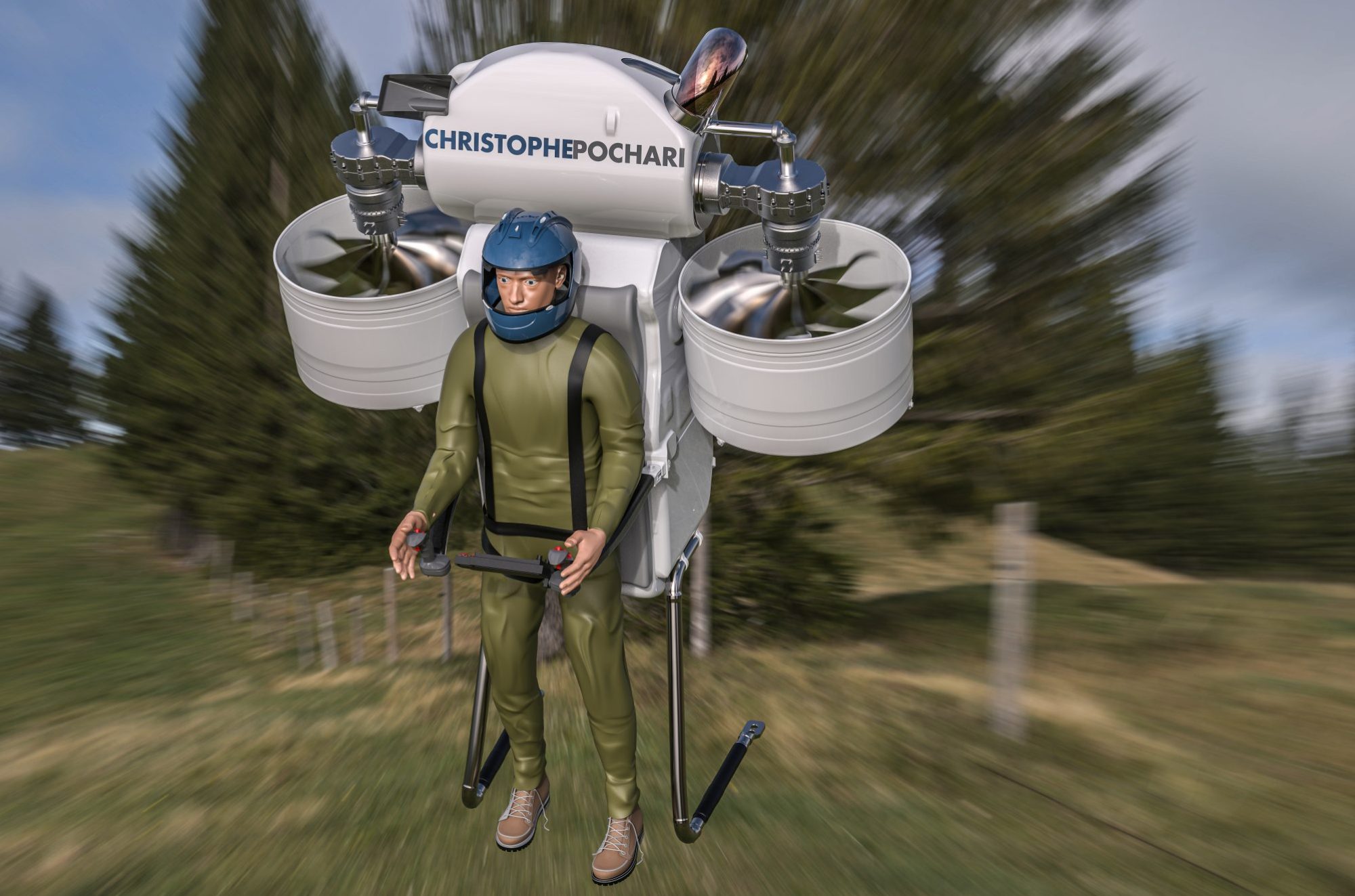
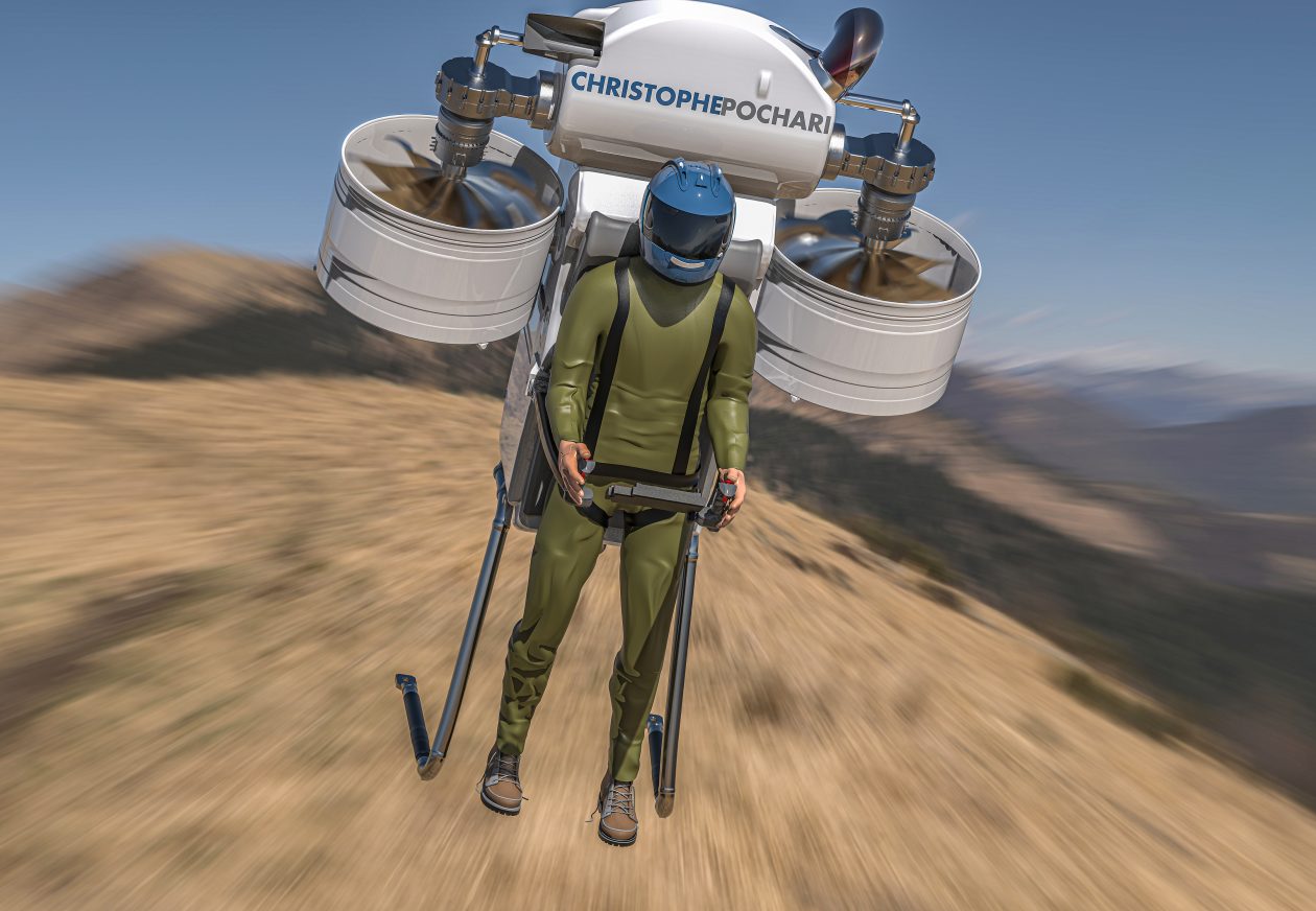
Christophe Pochari Energietechnik is developing a superior upgrade to the Martin Jetpack using high power density compound adiabatic cycle diesel engines for flight ranges up to 5 hours.
Process of Producing Calcium by Electrolysis, US3226311A, Jacques Van Diest, Solvay SA, 1963, Calcium Metal Production, US3043756A, George B Cobel, Paul R Juckniess, Dow Chemical Co, 1958. The above patents describe using barium and strontium chloride in the calcium chloride electrolyte bath to reduce the voltage required and hence the power consumption down to less than 9 kW/kg of calcium metal. 1.7 kg of calcium metal is required to reduce a kg of titanium, at an energy cost of 15.3 kWh/kg-titanium. Since the cost of high-altitude wind power is 1 cent/kWh or less, the electricity cost is only $150/ton-titanium. The Gibbs free energy for titanium dioxide reduction using metallic calcium is 332 kJ/mol. The chemical equation is as follows: TIO2 + 2Ca = Ti + 2CaO. The corrosive magnesium tetrachloride used in the Kroll process is eliminating dramatically reducing reactor and plant costs, the lower oxygen content of the titanium sponge produces a more ductile titanium product ready for alloying with vanadium. Vanadium can be extracted at low cost from magnetite.
In the 1970s the U.S. Army investigated using “adiabatic engines “. The U.S. Army hired Cummins to perform a study and build a prototype engine, unfortunately, nothing came of the program due to a lack of suitable lubrication options. An adiabatic engine is essentially an engine that rejects virtually no heat to its surroundings (the cooling system is eliminated altogether), such an engine could easily reach 55% brake thermal efficiency and above 60% with an COR, but due to its extremely high operating temperature, no lubricant could be found that did not experience excessive oxidation. A conventional piston engine rejects about 30% of the heat input to the coolant. An adiabatic engine only reduces coolant losses, so without turbo-compounding, the additional thermal energy is lost to the exhaust, making turbo-compounding an enabling technology to the adiabatic engine.
The adiabatic engine is Carnot’s dream, however, designing one to work in the real world is far from easy. Intense thermal loading on the cylinder wall imposes severe degradation upon the lubricant film, forcing designers to choose lubrication-free options. Designing a viable and practical adiabatic engine has historically proven difficult due to excessive cylinder wall temperature causing lubricant breakdown. The solution to this problem is to use a long ring-less cantilevered piston to capture the bulk of the hot combustion gases and rely on a secondary lubricated ringed piston to capture the remainder that has leaked passed the primary ringless piston. A gap of 150 microns is chosen allowing a small leakage rate of 50-60 liters per minute into the secondary piston. If the engine is operated at 4000 revolutions per minute, this leakage rate represents 5.8% of the combustion chamber volume per power stroke, but this gas enthalpy is not entirely loss, although the pressure drop across the 150-micron gap is large in design, these hot gases can still push down on the guide piston.
Development of the Minimum-Friction Adiabatic Engine, I. Kubo, S. R. Frisdrf, Cummins Engine Company, Inc., Columbus, Indiana, And, W. Bryzikj, U.S. Army Tank-Automative Command, Warren, Michigan
In the patent: Adiabatic Internal Combustion Engine, US4800853A, Charles E. Kraus, Charles B. Lohr, Excelermatic Inc, a similar arrangement is found, where the heat-exposed piston and combustion chamber are offset from the oil-lubricated seals.
“With this arrangement, the heat-resistant material surfaces of the piston and the cylinder are not in contact with one another and therefore need not be lubricated. Their temperature may therefore be permitted to be very high without causing any damage to the engine’s lubricant. The guide and seal structure of the cylinder wall which contains the seal rings and which is lubricated is sufficiently remote from the center of the combustion chamber so as not to be unduly exposed to the high combustion gas temperatures especially since, by the time the piston reaches its lower end of travel, the combustion gases are sufficiently cooled by expansion and extraction of energy.”
“As such pistons experience no substantial side thrust, and involve no problems of alignment of parts, they may be made to maintain separation from the cylinder by means of a film of air, thus dispensing with lubrication by oil. In the absence of oil lubrication cylinder cooling may be greatly reduced or even dispensed with, thus improving efficiency and simplifying construction.”
Gas-Llubricated Free Piston Engines with Supercharging Arrangements, US2983098A, Bush Vannevar, 1955
Gas-lubricated piston machine, DE3447459A1, Hartmut Prof. Dr.-Ing, Hensel Karsten Dipl.-Ing. Laing Oliver Dipl.-Phys, 1984
“The piston of a gas-lubricated piston machine is rotatably connected to a pushrod or a connecting rod. In order to build up a supporting gas film even during the dead center periods, the piston is made to rotate rapidly in relation to the cylinder wall. The pushrod of a two-stage piston machine can also be rotatably pivoted on the piston of the second stage so that the power-stroke forces of the two pistons are transmitted by the connecting rod of the second stage to the crank mechanism.”
“A gas lubrication structure is provided with a high-temperature-side cylinder, an expansion piston lubricated relative to the high-temperature-side cylinder by gas, and a layer provided to the outer peripheral surface of the expansion piston and composed of a material flexible and having a higher linear expansion coefficient than the base material of the expansion piston. The thickness of the layer under normal temperatures is not less than the size of the clearance formed between the layer and the high-temperature-side cylinder. Also, even if the layer is thermally expanded under use conditions, the layer under normal temperatures has a thickness enabling a clearance to be formed between the layer and the high-temperature-side cylinder.”
Gas Lubrication Structure for Piston, and Stirling Engine, US8763514B2, Hiroshi Yaguchi, Daisaku Sawada, Masaaki Katayama, Toyota Motor Corp, 2009
Oilless and Uncooled Diesel Engine Without Piston Rings With Adiabatic Operation, DE19651069C2, Lothar Strach
Engine cylinder and piston for an uncooled internal combustion engine, especially for a four-stroke diesel engine with exhaust turbocharger, DE3643828A1, Hubert Dr Grieb, MTU Aero Engines GmbH
Uncooled Oilless Internal Combustion Engine Having Uniform Gas Squeeze Film Lubrication, EP0330326B1, Wallace R. Wade, Vemulapalli Durga Nageswar Rao, Peter H. Havstad, Ford Werke GmbH
The Romance of Engines, by Suzuki, Takashi, 1997, SAE
The Adiabatic Engine for Advanced Automotive Applications, Roy Kamo, Adiabatics, Inc, Columbus, Indiana, USA
Christophe Pochari Energietechnik (de Rivals-Mazères Ingénierie) is reviving long-forgotten gas centrifuge technology for atmospheric carbon dioxide extraction to produce synthetic fuels such as jet fuel on aircraft carriers and to guarantee energy security through the production of kerosene, diesel and jet fuel for defense. The implications this technology has for military logistics is simply enormous.
Direct hydrogenation is redundant as it requires expensive iridium complexes, complicated ligand molecules (coordination complexes), it offers no advantage over simply producing additional hydrogen for reverse water gas shift. However, the direct hydrogenation of CO2 produces formic acid or methanol, which must further be reacted or decomposed to produce carbon monoxide until Fischer-Tropsch can be performed. Fischer-Tropsch is a highly mature process, it requires only earth-abundant elements for catalysis, namely cobalt and manganese. The TOF of these catalysts tends to be high resulting in a small reactor volume, the operating pressure is typically slightly over 2 MPa. The triatomic carbon-oxygen bond must be broken either way and this is accompanied by a large investment of energy. Copper/nickel supported on silica provides high conversion of CO, RWGS has been extensively for producing synthetic hydrocarbons on Mars. Copper catalysts have been widely studied for reverse water gas shift reactions, they also show high activity for the more common water gas shift reaction. Advances in micro-channel etching technology permit exothermic reactors like Fischer-Tropsch to be greatly process intensified, resulting in tiny footprints. Below are images of a microchannel Fischer-Tropsch reactors from the paper “Microchannel Reactor for Fischer–Tropsch Synthesis: Adaptation of a Commercial Unit for Testing Microchannel Blocks”, by Luciano C. Almeida.
Process intensified Fischer-Tropsch reactors featuring higher mass-transfer rates owing to high surface-volume ratios.
Christophe Pochari Energietechnik Christophe Pochari Energietechnik (Mazères Propulsion), is designing a complete package including the electrolysis bank for hydrogen production, the CO2 extraction centrifugation batch, the Fischer-Tropsch reactor, and the final hydrocarbon refining unit. This package can then be hooked up to any electrical power source to produce unlimited liquid hydrocarbon for armed forces around the world. We hope to supply NATO militaries such as the U.S, UK, France, etc, Another application will be trucking, airline, and civilian vehicle fleets that spend large sums on liquid fuels, by pairing up a CO2 centrifugation and Fischer-Tropsch plant to our high-altitude wind turbine operators can produce liquid fuels for less than $0.5/gallon. Even with the imminent end of the Ukraine war, long-term oil prices will remain over $70/bbl due to growing international demand and limited production elasticity. Moreover, hydrocarbons extracted from the sedimentary crust are contaminated with sulfur, nitrides, and other trace metals such as vanadium. Synthetic hydrocarbons are extremely clean and much clearer in appearance than “terrestrial hydrocarbons”. But besides fuel autonomy for armed forces and fleets, perhaps one of the most consequential aspects of this technology is energy storage for intermittent renewable sources such as wind and photovoltaic. Centrifuge and electrolyzer banks can be selectively switched on and off to match the prevailing electrical output of a variable power source like a wind turbine. This technology allows heavy-consuming countries like Germany and Japan with little to no gas and oil to produce their own liquid fuels using electricity only.
Centrifuge Specs:
Diameter: 300mm
Length: 1.5m
Rotational Speed: 80,000 rpm
Weight: 4.2 kg
Material: Toray T1100G CFRP
Peripheral Speed: 1256 m/s
Tangential Tensile Stress: 2860 MPa
Steady State Power Consumption: 0.5 kW
Bearing Type: Magnetic
Atmospheric CO2 Extraction Parameters: CO2: 1 bar inlet pressure, 1000 bar peripheral pressure
UF6 Benchmark Parameters: 0.13 bar sublimation pressure, 10 microbar center pressure, average pressure: 0.06 bar.
“A typical aircraft carrier can refuel every fighter jet about 20 times before depleting its supply of jet fuel.” An aggressive scenario assumes each fighter takes off once a day, in this scenario, the fuel supply would last 20 days. The typical aircraft carrier has a supply of 1 million gallons (3800 m3), or roughly 3150 tons worth of jet fuel. In order for the aircraft carrier to produce its entire fuel supply indigenously, it would require 210,000 tons of CO2 annually, or 247,000 m2. The total space required on a carrier is about 230,000 m2, so this is feasible if the centrifuges are stacked atop each other and the number of flights is reduced somewhat. Each to of kerosene consumes a minimum of 14 MWh of electrical power, 99% of which is found in the electrolysis of hydrogen to both produce the hydrogen for the hydrocarbon molecule itself and to break the carbon-oxygen bond. To produce 59,000 tons of kerosene annually would consume 815,000 MWh. The total installed electrical generation capacity on a Nimitz class carrier is 194 MW, so 48% of its power would be used to make kerosene, So clearly, this scenario is unrealistic both from a space and power perspective. A reduced usage scenario, around 10% of this estimate, or 10% of installed power, 19.4 MW, and 23,000 m2.
“Pressure therefore increases monotonically with the distance R from the center point of the centrifuge.”
Monte-Carlo Simulations of Centrifugal Gas Separation Roger Cracknell, Michael Golombok, a Shell Global Solutions (UK), Cheshire Innovation Park, Po Box 1, Chester, CH1 3SH, UK; B Shell Exploration and Production, Kessler Park 1, 2288 GS Rijswijk, the Netherlands
“The classical objection to using centrifugal gas separation industrially has arisen from the throughput restrictions associated with uranium isotopes. However, the restrictions for lighter gas separations are much less severe. Pressure is no longer limited by de-sublimation to sub-atmospheric levels. Radial pressure gradients are a factor of 10^4 less so that overall higher throughputs may be obtained for a given sized unit. The wall pressures are further reduced if we allow for the fact that, prior to diffusive separation of components, the mass transfer associated with setting up the radial pressure gradient takes place under thermodynamically adiabatic conditions. This variation from the usual isothermal assumption enables higher throughputs.”
Thermodynamic Factors Governing Centrifugal Separation of Natural Gas,M. Golombok, C. Morley.
“In fact, a number of methods are being investigated: there are various types of gas adsorbing crystal systems, there are membranes… but a few years ago, at Shell the imp of perversity prompted to me to suggest to the Shell Gamechangers (a mechanism for innovation) that we should look at mechanical separation of gases by centrifugation.”
Golombock, 2007, Difficult separations Citation for published version (APA): Golombok, M. (2007). Difficult separations. Technische Universiteit Eindhoven.
“A number of processes for producing hydrogen and other gaseous and liquid fuels from coal were developed and utilized prior to 1930. Use of these processes was nearly discontinued in the 1940s because of the great availability of natural gas and oil. However, the basic chemistry involved in these processes can again be utilized to produce desirable fuels, but the enormous advances in construction materials, process controls and instrumentation that have occurred in the last 40 years will allow the design of much better process plant hardware and more efficient processes. This proposal outlines an application of the modern high-strength composite materials to the design of a piece of process plant hardware for the separation of hydrogen from the other gases produced in the coal gasification process. The separation hardware will allow the chemical reaction process to be performed in a more efficient manner and may lead to new uses of hydrogen as a fuel. This separation technology can also be applied to the enrichment of natural gas which has too low a combustible content to be utilized directly.”
Application of Centrifugal Separation to the Production of Hydrogen from Coal, Laurence O. Williams.
There is, however, one other important difference arising from the different range of molecular weights in which we are interested and relating to the properties of UF6. The latter is a solid which sublimes at 56°C-at ambient temperature the vapor pressure is typically around 0.2 bar (Perry and Green, 1984). This means that during operation the pressure should never exceed this amount because this will lead to solid material precipitating on the wall which will severely damage operation. However, the pressure gradients for heavy molecular weight materials are extremely high. Consider a moderate range of operation, a centrifuge of radius 5 cm operating at 70,000 rpm. Based on equation (1) the pressure at the wall will be of the order of 14,000 times that at the center. Given the 0.2 bar operating limit at the wall, then the center pressure will only be of the order of 10 ubar. This results in a very low throughput and indicates one of the major paradigm shifts in going from isotope separation to industrial-scale natural gas separation.
Thermodynamic Factors Governing Centrifugal Separation of Natural Gas,M. Golombok, C. Morley.
Device Separating e.g. Gas Into Heavier Fraction, Has Outlet Opening Provided in Wall of Centrifugal Tube and Gas Removal Valve Provided in Wall of Outer Pressure Container for Outputting Heavier Fraction, DE102009013883A1, Herbert Widulle, 2009
A German chemist named Herbet Widulle patented a centrifuge for separating oxygen from nitrogen to produce medical-grade oxygen.
“The invention relates to a centrifuge for separating gaseous mixtures, comprising at least one hollow, mainly cylindrical rotor part which is rotatable in a housing and designed as a separating drum, which rotor part has at one end an end wall in which openings are provided close to the inside wall of the separating drum, this rotor part being provided with one stationary admission tube for the gaseous mixture to be separated, which admission tube is rigidly fastened to the housing, and with at least one outlet tube for the discharge of a first separation component, which tubes open into a separating chamber situated inside the separating drum, the rotor part being coupled to a driving motor and the centrifuge housing being provided with at least one connection for the discharge of a second separation component.
Such a centrifuge is known from the published Netherlands Pat. No. 103,433.
The application aims at further improving a centrifuge of the type mentioned in the preamble in such a way that it becomes suitable for separating a gas which could occur in very low concentration in vapour or mixtures of vapors. The application specifically aims at separating inert gases, such as helium, from natural gas. For this purpose, according to the invention, the space between the cylindrical outside of the rotor part and the inside of the part of the housing located opposite it, which space will hereinafter be called “expansion slot,” is provided with a number of throttling restrictors spaced at regular distances from each other, in such a way that this slot communicates, on the one hand, with the aforementioned openings and, on the other hand, with the connection for the discharge of the second separation component. As a result, the second separation component is removed from the separating chamber through the aforementioned openings, whereupon it is conveyed along the outside of the rotor part, while undergoing a gradual reduction of pressure, to the other rotor end, from where it is received by the aforementioned connection.
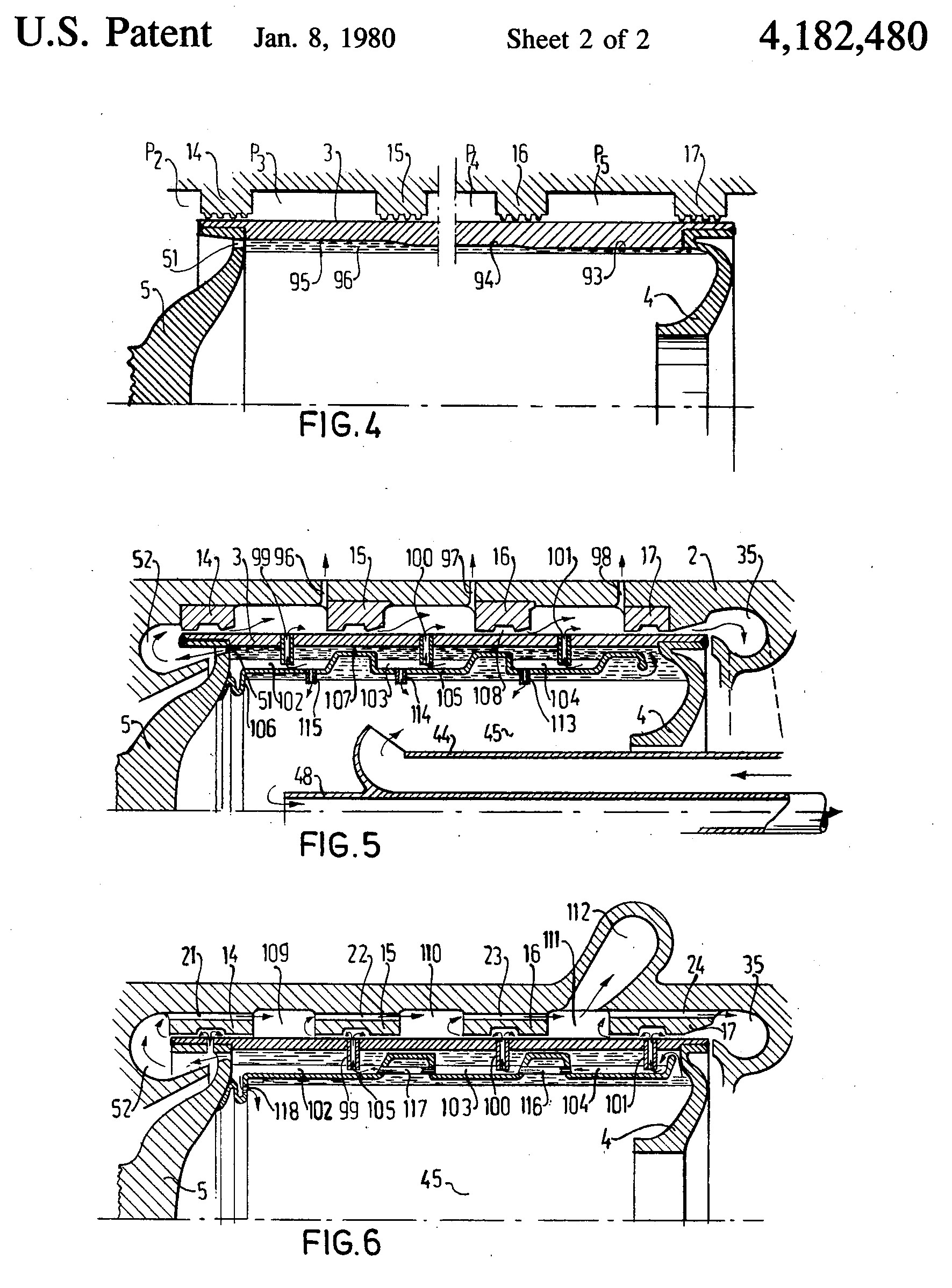
During the rotation, condensable gases such as CH4 and higher fractions of the natural gas are so extensively densified under the high concentration of pressure in the centrifuge drum that they liquefy against the inside wall of the drum, where they eventually form a thin layer of liquid. This is also where the heavier impurities become concentrated, such as mercury, nitrogen and the like.
This cannot become a thick layer, since liquid natural gas, which is subject to simultaneous expansion accompanied by partial evaporation, can flow off continuously through the aforementioned openings in the end wall of the separating space towards the space inside the housing but outside the drum. From there, this partly liquid gas flows at a pressure p2 through the first of a series of restrictors which are arranged in the slot, during which process the pressure is relieved to a lower value p3. This is governed by the rule that p1 /p2, just as p2 /p3, is equal to the critical pressure ratio. The gas, although cooling down as a result of expansion during this relief of pressure, is heated at the same time on account of the heat transfer from the layer of liquid natural gas inside the drum, which heat moves through the drum wall of the centrifuge. Eventually, therefore, the temperature in the expansion slot remains substantially constant. This process is repeated at all restrictors except the last. In the last restrictor, the medium in the expansion slot is no longer heated by heat from the layer of liquid natural gas inside the centrifuge drum. This medium leaves the centrifuge after the last expansion. It is an important aspect of the invention that the throttling restrictors in the expansion slot are designed as a number of bearings which surround the rotor and support it along the entire periphery, mutually separated by expansion chambers. The drum is thus adequately supported from distance to distance over the entire length of the drum, so that quiet running of the drum is ensured. Such a bearing is preferably provided in the form of a gas-film bearing or of a spiral-groove gas bearing, because this enables the second separation component to flow through the spiral-groove passages to the other side of the bearing. Such a bearing is also designed effectively as a viscoseal. In order to prevent the possibility of insufficient medium flowing through the lubricant film space of a bearing to the other side, a bearing house is provided, if necessary, with at least one bypass for connecting the front and the rear side of the bearing to each other. The pressure on the outside of the drum is very high at the beginning of the expansion, its maximum being almost as high as in the thin liquid layer inside the drum, but it becomes gradually lower to the measure that more restrictors have been passed. Accordingly, the drum is exposed to a higher outward differential pressure near the inlet of the gas into the drum than near the outlet of the liquid gas as it leaves the drum. The drum will therefore expand more greatly at the inlet end if the wall thickness is kept constant. In order to enable the bearings to follow this rotor-drum deformation, which changes from place to place, a bearing is interrupted on the periphery by a dilation slot, so that the bearing can perform a flexible motion.
With regard to wall thickness, the centrifuge housing can be adapted to the local pressure in the expansion slot, in the sense that the wall thickness increases to the measure that the maximum operating pressure in the expansion slot has a higher value. According to a preferred embodiment, the outlet tube for the first separation component extends inside the rotor into or near the coolest part thereof. As a result, the first component is drained at a point where the vapour pressure of the second medium is as low as possible, so that the concentration of the inert gas, such as helium, is high for that very reason, allowing the first component to be drained with the highest possible helium enrichment.
It can be advantageous to provide the centrifuge with a two-part rotor, in such a way that those end walls of each rotor part which are furnished with openings face each other, while being connected by a central portion. In such case, the need for a collar bearing to absorb the axial pressure is obviated. This embodiment greatly simplifies the installation of the driving electromotor, since it can be so fitted that its armature coincides with the aforementioned central portion. The stator of such an electromotor is provided as a canned stator, around which the liquid natural gas flows. In order to avoid trouble from certain critical speeds of the centrifuge drum, it is preferably so manufactured that the drum wall exhibits at regular intervals a constriction in the form of a circular slot along the periphery. Such circular slots can be provided along the inside periphery as well as along the outside periphery. In the places where such a slot-shaped groove occurs, the drum wall is somewhat more flexible, allowing the critical speeds of the rotor drum to be made so low that they are smaller than the operating speed. It is thus made impossible for these frequency ranges to interfere with each other. The expansion space located outside the separating drum can be provided with means for separate discharge of liquid, so that the expansion slot contains substantially the gaseous second separation pressure separation component, so that the jacket friction on the outside of the centrifuge drum is appreciably reduced. In this embodiment, the bearings which embrace the drum are provided in the form of gas bearings. In order to load the drum wall more uniformly, the inside diameter of the drum can be made large in an area marked by a high outside pressure, and conversely. As a result, the liquid layer of the first separation component, and therefore the internal load, increases in magnitude in places of a high outside pressure, and decreases in magnitude where the outside pressure is low. Expansion chambers can also be arranged inside the drum, as will be described hereinafter. This causes the gas pressure to be lowered on the outside of the drum, with a corresponding decrease of the frictional resistance losses.
With the use of several of the centrifuges described, a centrifuge cascade can be so built up that these centrifuges communicate with each other on their gas sides, in such a way that the degree of enrichment of the first component increases at each subsequent centrifuge. The first component can then be abstracted at the top of the cascade, this component containing to a high degree the desired gas, for example helium. This component is then discharged to an installation for burning the entrained residues of the second component, which consists substantially of hydrocarbons, whereupon the resultant gaseous mixture is supplied to an installation for freezing the impurities out of the desired inert gas.
Assignee: Ultra Centrifuge Nederland N.V., The Hague, Netherlands
Inventors: Frederik H. Theyse, Bensberg-Herkenrath, Fed. Rep. of Germany; Fridtjof E. T. Kelling, Amsterdam, Netherlands
Appl. No.: 802,900 22 Filed: Jun. 2, 1977
Patent name: Centrifuge for Separating Helium From Natural Gas